download InnovMetric PolyWorks 2016 IR9 x86 x64 full license forever
Link download InnovMetric PolyWorks 2016 IR9 32bit 64bit full crack
InnovMetric PolyWorks 2016 IR9 32bit 64bit full crack
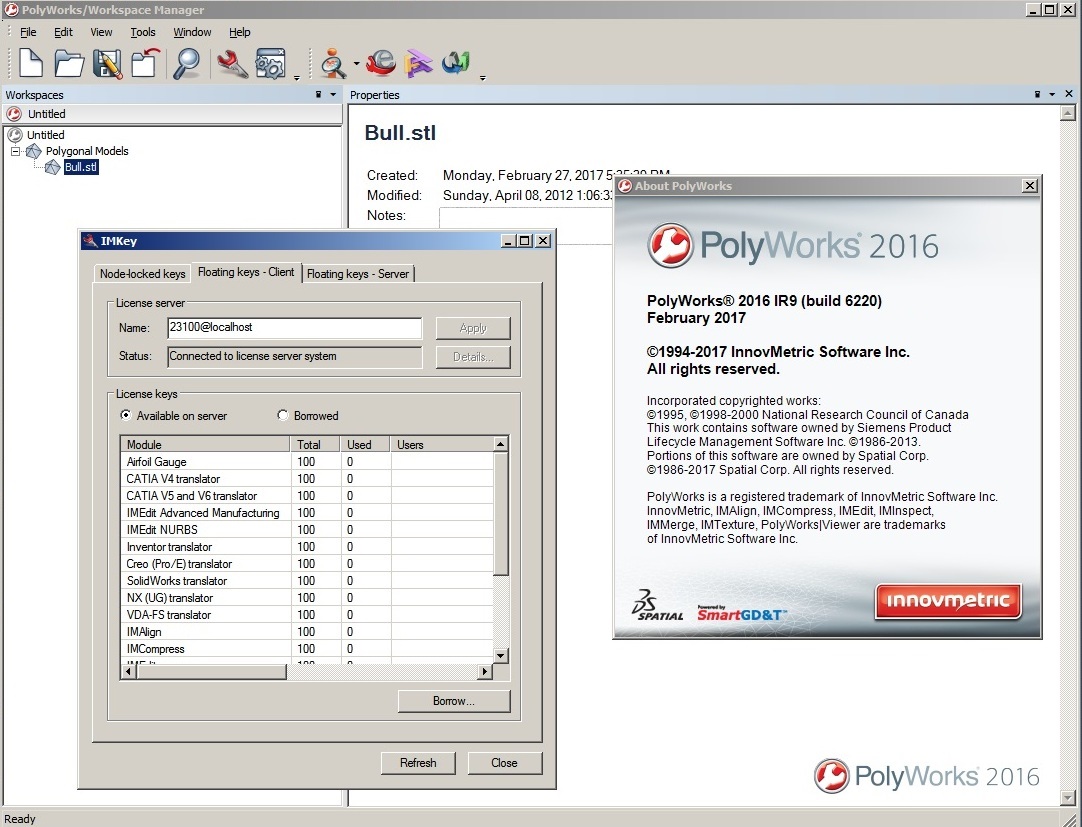
InnovMetric PolyWorks 2016 IR9 x86 x64 full license forever
Description: PolyWorks (PW) – multifunctional software production company InnovMetricSoftwareInc, used for processing of laser scan data: reverse engineering, control of geometry of products, problems of architecture, monitoring, ground deformation, and many others.. PolyWorks software package allows you to work quickly and efficiently with very large amounts of data. PolyWorks consists of several modules and has a wide range of tools that simplify and speed up the work with the data. It is important to note that the complex allows you to work with data obtained from the three-dimensional scanners of all brands.
IMAlign
• This unit is designed for primary data.
• Initially, import the data obtained by ground-based three-dimensional scanner, or data is being processed in other programs. Already at this stage, there are some treatment options: the data is imported with a given accuracy (point sampling step is set); Data can be filtered by distance.
• Produced primary processing point clouds: scaling point clouds; Filtering for matching points, ie, ordering (point diverging distance below a settable, deleted). The module binds to the external coordinate system and the cross-linking scans.
• The program allows you to choose the method of cross-linking, which can be divided into: visual linking methods; for the reference objects. And not least: the program produces statistics and histograms combining errors, create a primary polygonal models.
• Data can be eskportirovanny in many formats (AC, BRE, PIF, PTX, SURF) and a polygonal model in DXF, IGES.
IMMerge
• It is intended to create a triangulated model, the module allows you to manually define the parameters responsible for the quality and accuracy of the generated models.
IMEdit
• The module is designed to work with a TIN-surfaces created in PW or imported from other programs.
• The module contains the functions of smoothing, filling the “holes”, retriangulyatsii (some areas can be re-triangulated with less accuracy), a variety of mechanisms for creating curves and tools to edit them.
• This module provides functions for creating and editing surface NURBS– surfaces that are created from the curves, the module provides a variety of ways to create these curves manually – defined curves are carried out on these points, the curves are based on intersections with model planes, loft automatically compiled mesh curves on the model with a given accuracy (pitch and the maximum distance at which they are spaced from the model).
IMInspect
It includes tools to:
• produce writing in a cloud of geometric primitives points (circle, cone, cylinder, plane, point, polyline, and a vector scope);
• construction of polygonal surfaces;
• unification of data and reference objects in a single and unique system of coordinates;
• profiling, creating arbitrary and predetermined sections;
• make a detailed comparison, statistics, and reports within or between data, reference objects and primitives;
• all types of measurement, position control and the state of complex structures (measurement of geometric dimensions, both linear and angular, area, volume);
• export data and reference objects in many formats.
IMCompress
• Decrease mainly colored polygon of 3D-models. Support module, which allows to reduce the weight of the model by reducing the number of its constituent elements (triangulation or patches).
IMTexture
• The module allows you to combine the model and texture map it, ie, get a model with textures mapping not only the geometry, but also the physical properties of the model. The texture map must be obtained from the scanner, that is, the data from the scanner should be in addition to coordinate information on the intensity. It combines two types of data, as a result of the model is closest to reality.
IMView
• Module for viewing data.
• Models created in a program stored in an internal format and can be viewed in the free module supplied. PolyWorks software product designed for a specific range of tasks which in other software products is not possible.
• This range of tasks covers many aspects. For example: Monitoring of ground deformation, landslides and subsidence of soil under the influence of anthropogenic factors. By overlapping models created at different times, you can get the amount and direction of displacement. And characterize data on these displacements will not separate checkpoints.
• Since the scanning performed continuous shooting, the necessary information will be available in almost any point on the surface. The data obtained are presented in the form of a dyed three-dimensional color distribution pattern depending on the strain.
• A simple click of the mouse button at any point of the model on the screen displays the value and direction of the deformation, as well as the coordinates of the point of observation in different cycles. Then the distribution charting these quantities, which can be transformed into various charts, graphs and histograms in MS Excel format.
• Three-dimensional model of the earth’s surface can solve a number of tasks, from calculating the explosive unit volumes at existing open pits and ending with the usual topographical plans and materials for land use documentation.
• Tools PolyWorks software product automatically in this case may also solve the following problems:
Analysis of the surfaces (the magnitude and direction of deformation). Analysis of surfaces – sections (can be done in different directions perpendicular to the board and horizontal planes: in the first case, it is one of the main parameters of quality assessment of the explosion and the location of the ore, in the other we get topoplan career).
• Construction of the surface contour of collapse. Evaluation of the collapse and explode volume (estimate by the collapse of these models can be performed as follows: the collapse of the settlement is divided into blocks (eg 3 × 3 m) and the estimated amount of each such unit; these calculations are calculated from a plane at a given elevation) Many other tasks. The objectives of industrial enterprises related to the measurements of inaccessible and complex objects, building three-dimensional models of objects and training materials for use in automated systems engineering and enterprise management systems. Monitoring the condition of buildings and structures, in particular, observations of deformations.
• By overlapping models created at different times, you can get the amount and direction of displacement at any point in the building. Did the imposition of the current model to some “reference” model, which may play a role design. In this case, we’ll have a deviation from the “ideal” parameters. An example of such a strain may be sagging hip roof.
• The deformation monitoring is carried out both on the whole building, and on certain structural elements, including the disabled.

For downloading this full software, click download sysmbol and check out. The link will be appeared after your payment aytomatically.
Any problem for download, install, contact admin for support: [email protected]
Thanks