download GibbsCam 2010 v9.5.1 32bit 64bit full crack 100% working
link download GibbsCam 2010 v9.5.1 win32 win64 full license
GibbsCam 2010 v9.5.1 x86 x64
Machining with GibbsCam 2010 v9.5.1 full license
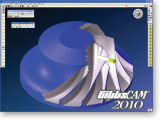
GibbsCAM 2010 is an automated program preparation system for CNC machines, combining ease of use and functional power. The basic functionality of the system can be expanded by adding specialized modules. An intuitive user interface provides easy access to the management functions of geometry, tools, trajectories, verification and postpotsessirovaniem. Flexible programming methods allow you to quickly create optimal processing programs. Debugged processing processes can be saved and reused using the knowledge base. Modeling functions help to prepare geometry for processing needs by creating wireframe, surface and solid geometry. The built-in mechanism for simulating the removal of material accurately displays the entire processing process, showing both the change in the geometry of the workpiece, and all possible collisions. The result of the calculation can be compared with the initial geometry of the model, discovering the remnants of the material or cuts. Full associativity between geometry, process parameters and trajectories allows you to quickly change the model and processing parameters and automatically receive the adjusted trajectories.
The following types of machines are supported:
– Milling with simultaneous control of 2 – 5 axes;
– Turning one- and two-spindle, with any number of calipers, with software-controlled auxiliary mechanisms (tailstocks, lunettes, catching parts …);
– Turning and milling one- and two-spindle, with any number of supports, with software-controlled auxiliary mechanisms, with simultaneous control of 2 to 5 milling axes;
– Multi-tasking turning and milling machines with multi-channel control without the limitation of the number of control channels, including longitudinal turning machines (so-called swiss-type machines);
– Erosive two- and four-axis.
Milling
– Stripping the workpiece plane;
– Roughing and contouring 2-axis processing of prismatic elements;
– Rough 3-axis machining;
– Finished 3-, 4- and 5-axis machining using more than a dozen different schemes of tool movement;
– Multipass 4 and 5-axis machining;
– Drilling material for roughing;
– Centering, drilling, countersinking, boring, unfolding holes;
– Thread tapping;
– Thread milling;
– Engraving on the plane and surface;
– Machining on 3-axis machines with one rotary axis;
– Performing programmable measurements using machine tools;
– Are used restrictions on the depth of processing, as well as defined as the prohibition zones of processing or its limitations;
– All faces not selected for processing are considered control faces, which can not be cut;
– In the processing mode of the assembly, all the equipment is automatically dispensed.
The following types of tools are used:
– End mills;
– End cutters with rounded and non-rounded edges, spherical end mills, conical and straight;
– Shaped cutters (radius, dovetail, fungal, ball);
– Shaped cutters, the contour of which is drawn by the programmer;
– Tools for machining holes – centering, drills, countersinks, scrapers, boring;
– Taps;
– Single-row and multi-row thread cutters;
– Standard and programmed by the programmer mandrel.
Turning
– Treatment of the front and rear ends;
– Roughing and contouring of external and internal contours;
– Draft and contour boring of internal circuits;
– Roughing and contouring of external and internal grooves;
– Cutting operations;
– Centering, drilling, countersinking, boring, unfolding holes;
– Thread tapping;
– Turning of external and internal threads;
– The transfer of the part from the spindle to the spindle without limiting the number of such transmissions;
– Use of any number of calipers;
– Management of tailstock, lunettes, safety devices, feed systems;
– Accounting of cartridges, including different for different spindles.
The following types of tools are used:
– Incisors with plates of rhomboid, rectangular, square, round, hexagonal, triangular, threaded;
– Incisors with shaped plates, the contour of which is drawn by the programmer;
– Tools for machining holes – centering, drills, countersinks, scrapers, boring;
– Taps.
Turning and milling processing
When programming the turning-milling processing, all the types of lathe and milling operations described above are combined and all of the listed types of tools are used. Turning and milling operations can be alternated in any order. In addition, it is possible to perform the following milling operations:
– Machining with the desired orientation of the part relative to the C axis;
– Machining with continuous rotation of the workpiece around the C axis;
– “Winding” of flat machining, including engraving, on a cylinder;
– Use of different types of interpolation during milling.
When programming lathe-milling processing on machines with multichannel control, all the types of lathe and milling operations described above are also available for use and all of the listed types of tools are used. In addition, it is possible to perform the following service operations:
– Synchronization of simultaneous operations at their beginning or end with the possibility of waiting for each other’s instruments near the part or with the tapping away from it opposite to the synchronized at the end or the beginning of the operation;
– Inline synchronization of the turning operations performed simultaneously on one part with explicit indication of the amount of mutual shift of the tools along the axis of the workpiece;
– Automatic verification of various kinds of synchronization errors, such as an attempt to perform simultaneous execution of turning and milling operations on one part or use of one tool for processing two different parts simultaneously;
– Automatic correction of cutting modes performed simultaneously on one detail of turning operations.
Erosion treatment
– 2-axis processing of closed and open circuits;
– 2-axis machining of contours with slope;
– Processing with the creation of jumpers and without them;
– Full burning of material inside the contour;
– Creation in one operation of the vertical and inclined parts of die dies;
– 4-axis processing of closed and open circuits;
– Management of approach and taps, modes of cutting;
– The machine’s limitations on the allowable wire angles are taken into account;
– The cutting technology settings are taken into account.
Processing of surface and solid models
Creation of hybrid surface and solid models of parts and tools. Correction of imported geometry with special surface correction functions for obtaining a solid model. Removing superfluous from the point of view of processing surfaces with the possibility of breaking the body on the surface. Interactive selection of elements allows you to quickly determine the processing areas, and the technology of automatic selection of elements speeds up the processing of holes.
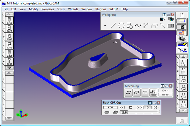
3-axis machining and OSR
It complements the basic capabilities of milling processing by creating and processing surface and solid geometry. A wide range of 3-axis parts is supported, including the actual parts of products of all industries, mold molds, inserts, electrodes, plates and the like. Applying several processing processes to several faces in one operation with automatic device traversal. Creation of free from cuts 3-axis trajectories on the model of the part with the possibility of processing contours and pockets, finishing with parallel passes and cleaning of surface joints. NURBS-interpolation is supported for high-speed processing. Also, the “smooth” approximation of NURBS geometry by polylines and arcs is supported. Supports the entire spectrum of BSS elements, including the management of approaches and taps, the height of the scallop processing, smooth transitions, rounding corners.
4-Axis and 5-Axis Machining
Create 4-axis trajectories by “winding” simple machining on the cylinder or directly on the part model. The axis of the tool can look at the axis of the part or shift with the control of its inclination angle. For the most difficult cases of processing, there are functions of simultaneous 5-axis machining with the complete exception of material conflicts with the tool and cartridge and support for all types of tools (end mills, rounded, spherical, tapered, ball bearings).
Multifunction machines
Creating optimal programs for multifunction machines with several calipers or groups of tools and spindles. Graphic synchronization of job flows and simple synchronization of operations for several groups of tools. Programming of spindles, tool traps, tailstocks and other controlled mechanisms. Supports of longitudinal turning (Swiss-type) are supported. Delivered postprocessors guarantee the receipt of ideal programs.
Simulation of the machine
Checking the complex movements of the tool on the machine model to ensure that the tool does not conflict with the tools, parts of the machine and the workpiece, before executing the program in the workshop, avoids costly mistakes.
Data exchange with CAD-systems
Reading data from all common CAD systems with a rich set of settings for the exchange process. Support for DXF / DWG, ACIS SAT, Parasolid, VDA-FS, STEP AP203 and 214 formats, as well as direct reading of Autodesk Inventor, CATIA V4 and V5 files, KeyCreator, Pro / ENGINEER Wildfire, Rhinoceros, Solid Edge, SolidWorks. There are additions to the Mechanical Desktop, Inventor, KeyCreator, Rhinoceros, Solid Edge, and SolidWorks systems for direct transfer of the model to GibbsCAM.
Postprocessors
Creation of own postprocessors on the basis of supplied standard templates. For maximum levels of complexity and optimization, you can choose the desired postprocessor, working on the ideology of “what I see and process” (WYSIWYM – “what-you-see-is-what-you-machine”) from a library containing over 7000 developed for different Combinations of machine / postprocessors. Library postprocessors can be further refined taking into account any specific requirements. To use older postprocessing systems, there is output of programs in the APT format (or CL-data).
Programming at the machine
System Gibbs SFP (from Shop Floor Programming – programming at the machine), created for use in control racks based on personal computers. The graphical user interface offers effective basic programming capabilities directly on the machine rack for rapid creation and modification of programs. Gibbs SFP is fully compatible with all GibbsCAM modules, which ensures data transfer of any complexity between the workshop and the programming department.
Gibbs SFP is selected by many leading manufacturers of machines and racks, which makes Gibbs and Associates a leading supplier of guild programming systems.
If you want to download GibbsCam 2010 v9.5.1, please click to DOWNLOAD symbol and complete check out a little help my website is maintained. The download link is appeared automatically when you complete check out.

Please see youtube video for download instruction by open *.txt file and copy youtube video link paste to your browser If you don’t know how to download.
Inside folder GibbsCam 2010 v9.5.1, already have crack’s file and instruction how to install GibbsCam 2010 v9.5.1 step by step. I guarantee you can install GibbsCam 2010 v9.5.1 successfully if you follow that instruction.
If you also can not install it or any problems, please contact to me by email: [email protected], then I will help you to install software by teamviewer.
Thanks a lot