download Build Your Own CNC Machine books pdf
download Build Your Own CNC Machine books pdf
How to Build Your Own CNC Machine with guide books
Build Your Own CNC Machine tutorials pdf
build your own CNC machine ebook
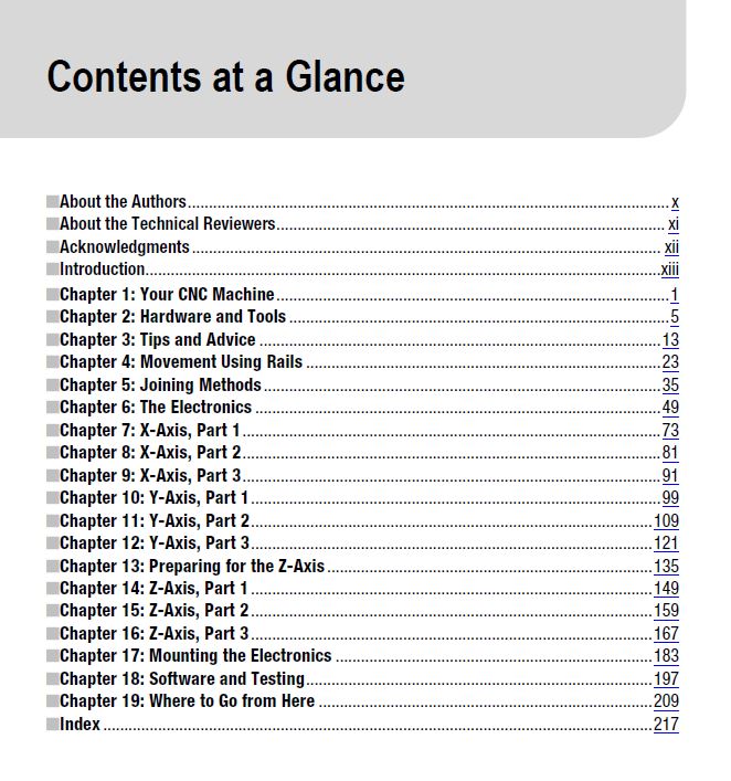
contents at a glance of build your own CNC machine
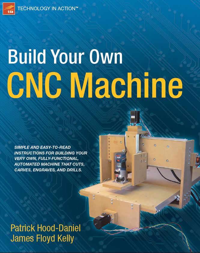
Do you like to build things? Are you ever frustrated at having to compromise your designs to fit whatever parts happen to be available? Would you like to fabricate your own parts? Build Your Own CNC Machine is the book to get you started. CNC expert Patrick Hood-Daniel and best-selling author James Kelly team up to show you how to construct your very own CNC machine. Then they go on to show you how to use it, how to document your designs in Computer-Aided Design programs, and how to output your designs as specifications and tool paths that feed into the CNC machine, controlling it as it builds whatever parts your imagination can dream up.
Don’t be intimidated by abbreviations like CNC and terms like Computer-Aided Design. Patrick and James have chosen a CNC-machine design that is simple to fabricate. You need only basic woodworking skills and a budget of perhaps $500 to $1,000 to spend on the wood, a router, and various other parts that you’ll need. With some patience and some follow-through, you’ll soon be up and running with a really fun machine that’ll unleash your creativity and turn your imagination into physical reality.
The authors go on to show you how to test your machine, including configuring the software.
Provides links for learning how to design and mill whatever you can dream up
The perfect parent/child project that is also suitable for scouting groups, clubs, school shop classes, and other organizations that benefit from projects that foster skills development and teamwork
No unusual tools needed beyond a circular saw and what you likely already have in your home toolbox
Teaches you to design and mill your very own wooden and aluminum parts, toys, gadgets—whatever you can dream up
What you’ll learn
Build your very own CNC machine
Learn about linear movement and motion transmission
Who is this book for?
Build Your Own CNC Machine is the perfect book for hobbyists who like to build and create using wood and metal. It’s especially for those who have ever been foiled by lack of specific parts to help realize their creative designs. Build Your Own CNC Machine is also an excellent choice for organizations such as scouting and church groups, school shop classes, and so forth, as it provides an educational project of modest cost that all can work on together.
Contents
■About the Authors …………………………………………………………………………………………………… x
■About the Technical Reviewers ……………………………………………………………………………….. xi
■Acknowledgments ………………………………………………………………………………………………… xii
■Introduction ………………………………………………………………………………………………………….. xiii
■Chapter 1: Your CNC Machine …………………………………………………………………………………. 1
What is CNC? ……………………………………………………………………………………………………………… 1
Industrial Uses ……………………………………………………………………………………………………. 2
Personal Uses …………………………………………………………………………………………………….. 2
Your DIY CNC Machine …………………………………………………………………………………………………. 3
What’s Next? ………………………………………………………………………………………………………………. 4
■Chapter 2: Hardware and Tools ………………………………………………………………………………. 5
The Tools …………………………………………………………………………………………………………………… 5
The Electronics Vendors ……………………………………………………………………………………………… 12
What’s Next? …………………………………………………………………………………………………………….. 12
■Chapter 3: Tips and Advice …………………………………………………………………………………… 13
Cut Once ………………………………………………………………………………………………………………….. 13
Protect Yourself …………………………………………………………………………………………………………. 14
Protect Your Lungs …………………………………………………………………………………………………….. 15
Label Parts ……………………………………………………………………………………………………………….. 16
MDF Sheets and Sizes ………………………………………………………………………………………………… 17
Limit Your Cuts ………………………………………………………………………………………………………….. 18
Time Your Cuts ………………………………………………………………………………………………………….. 20
Encouragement …………………………………………………………………………………………………………. 20
What’s Next? …………………………………………………………………………………………………………….. 21
■Chapter 4: Movement Using Rails ………………………………………………………………………… 23
Bearing-Rail Assembly ……………………………………………………………………………………………….. 23
Riding the Rail …………………………………………………………………………………………………………… 32
Tips and Advice …………………………………………………………………………………………………………. 33
What’s Next? …………………………………………………………………………………………………………….. 33
■Chapter 5: Joining Methods ………………………………………………………………………………….. 35
Two Pieces of MDF ……………………………………………………………………………………………………. 35
Method 1: Cross Dowels ……………………………………………………………………………………………… 38
Method 2: Bolt, Washer, and Nut ………………………………………………………………………………….. 43
Which Method Is Best? ……………………………………………………………………………………………….. 44
Building a Jig to Drill ………………………………………………………………………………………………….. 45
What’s Next? …………………………………………………………………………………………………………….. 47
■Chapter 6: The Electronics ……………………………………………………………………………………. 49
The Required Components ………………………………………………………………………………………….. 49
Preparing the Stepper Motor Wires ……………………………………………………………………………….. 53
Preparing the Power Supply ………………………………………………………………………………………… 56
Preparing the Breakout Board………………………………………………………………………………………. 59
Providing Power to the Stepper Motor Drivers …………………………………………………………………. 62
Wiring Motor Drivers to the Breakout Board ……………………………………………………………………. 64
Connecting Power to Motor Drivers ………………………………………………………………………………. 65
Connecting Stepper Motors to Motor Drivers ………………………………………………………………….. 67
Wiring the Cooling Fan ……………………………………………………………………………………………….. 69
Testing the Electronics ……………………………………………………………………………………………….. 70
What’s Next? …………………………………………………………………………………………………………….. 71
■Chapter 7: X-Axis, Part 1 ………………………………………………………………………………………. 73
The X-Axis MDF Parts …………………………………………………………………………………………………. 73
The X-Axis Table ……………………………………………………………………………………………………….. 74
Cutting Rails for Tabletop Sides ……………………………………………………………………………………. 79
Summary of Work ……………………………………………………………………………………………………… 80
What’s Next? …………………………………………………………………………………………………………….. 80
■Chapter 8: X-Axis, Part 2 ………………………………………………………………………………………. 81
Drilling the Table ……………………………………………………………………………………………………….. 81
Drilling Holes for Legs ………………………………………………………………………………………………… 85
Cutting the Table Ends ……………………………………………………………………………………………….. 86
Summary of Work ……………………………………………………………………………………………………… 90
Hardware Required ……………………………………………………………………………………………………. 90
What’s Next? …………………………………………………………………………………………………………….. 90
■Chapter 9: X-Axis, Part 3 ………………………………………………………………………………………. 91
Drilling the Table Ends (Legs) ………………………………………………………………………………………. 91
Drilling and Mounting the Rail ……………………………………………………………………………………… 95
Attaching the Table Legs …………………………………………………………………………………………….. 96
Cutting the X-Axis Lead Screw …………………………………………………………………………………….. 97
Summary of Work ……………………………………………………………………………………………………… 98
Hardware Required ……………………………………………………………………………………………………. 98
What’s Next? …………………………………………………………………………………………………………….. 98
■Chapter 10: Y-Axis, Part 1 …………………………………………………………………………………….. 99
The Y-Axis MDF Parts …………………………………………………………………………………………………. 99
Parts Q and R: The Y-Axis Gantry Sides ……………………………………………………………….. 100
Building BRAs for Gantry Sides…………………………………………………………………………… 105
Summary of Work ……………………………………………………………………………………………………. 108
Hardware Required ………………………………………………………………………………………………….. 108
What’s Next? …………………………………………………………………………………………………………… 108
■Chapter 11: Y-Axis, Part 2 …………………………………………………………………………………… 109
The Y-Axis MDF Parts ……………………………………………………………………………………………….. 109
Attaching BRAs and Gantry Sides ……………………………………………………………………………….. 110
Part P: The Y-Axis Gantry Bottom Support ……………………………………………………………………. 114
Summary of Work ……………………………………………………………………………………………………. 119
Hardware Required ………………………………………………………………………………………………….. 120
What’s Next? …………………………………………………………………………………………………………… 120
■Chapter 12: Y-Axis, Part 3 …………………………………………………………………………………… 121
The Y-Axis MDF Parts ……………………………………………………………………………………………….. 121
The Rail Support ………………………………………………………………………………………………………. 122
Finishing the Y-Axis Frame ………………………………………………………………………………………… 128
Tips on Final Frame Assembly ……………………………………………………………………………………. 132
Summary of Work ……………………………………………………………………………………………………. 132
Hardware Required ………………………………………………………………………………………………….. 132
What’s Next? …………………………………………………………………………………………………………… 133
■Chapter 13: Preparing for the Z-Axis ………………………………………………………………….. 135
The Y-Axis BRA Supports ………………………………………………………………………………………….. 135
Cutting and Drilling Parts C and D ………………………………………………………………………………. 136
Measuring for the Z-Axis …………………………………………………………………………………………… 144
Summary of Work ……………………………………………………………………………………………………. 146
Hardware Required ………………………………………………………………………………………………….. 147
What’s Next? …………………………………………………………………………………………………………… 147
■Chapter 14: Z-Axis, Part 1 …………………………………………………………………………………… 149
The Z-Axis MDF Parts ……………………………………………………………………………………………….. 149
Part F: The Z-Axis Rail Support …………………………………………………………………………………… 150
Parts W and X: The Z-Axis Bearing Supports ………………………………………………………………… 154
Z-Axis Bearing-Rail Assemblies ………………………………………………………………………………….. 155
Summary of Work ……………………………………………………………………………………………………. 157
Hardware Required ………………………………………………………………………………………………….. 157
What’s Next? …………………………………………………………………………………………………………… 157
■Chapter 15: Z-Axis, Part 2 …………………………………………………………………………………… 159
Preparing to Drill ……………………………………………………………………………………………………… 159
Drilling Part F: The Z-Axis Rail Support ………………………………………………………………………… 159
Drilling Parts W and X: The Z-Axis Bearing Supports ………………………………………………………. 161
Mounting the Z-Axis Bearing-Rail Assemblies ……………………………………………………………….. 164
Summary of Work ……………………………………………………………………………………………………. 166
Hardware Required ………………………………………………………………………………………………….. 166
What’s Next? …………………………………………………………………………………………………………… 166
■Chapter 16: Z-Axis, Part 3 …………………………………………………………………………………… 167
Cutting the Z-Axis Rail Support Rails …………………………………………………………………………… 167
Cutting and Drilling Parts M and N ……………………………………………………………………… 169
Cutting and Drilling Part V …………………………………………………………………………………. 173
Assembling the Z-Axis ………………………………………………………………………………………………. 174
Attaching the Z-Axis to the Machine ……………………………………………………………………………. 176
Summary of Work ……………………………………………………………………………………………………. 181
Hardware Required ………………………………………………………………………………………………….. 181
What’s Next? …………………………………………………………………………………………………………… 181
■Chapter 17: Mounting the Electronics …………………………………………………………………. 183
Cutting and Drilling the Motor Mounts …………………………………………………………………………. 183
Mounting Your Router ……………………………………………………………………………………………….. 191
Summary of Work ……………………………………………………………………………………………………. 194
Hardware Required ………………………………………………………………………………………………….. 195
What’s Next? …………………………………………………………………………………………………………… 195
■Chapter 18: Software and Testing ……………………………………………………………………….. 197
CAD, CAM, and Control Software ………………………………………………………………………………… 197
The Mach3 Control Software ……………………………………………………………………………………… 197
Downloading and Installing Mach3 ……………………………………………………………………………… 198
Configuring Mach3 …………………………………………………………………………………………………… 200
Ports and Pins …………………………………………………………………………………………………. 200
Motor Outputs …………………………………………………………………………………………………. 201
Input Signals …………………………………………………………………………………………………… 201
Motor Tuning and Setup ……………………………………………………………………………………. 202
Configuring the Default Motor Units ……………………………………………………………………. 203
Testing Your Machine ……………………………………………………………………………………………….. 203
Testing the Router ……………………………………………………………………………………………………. 206
School Starts …………………………………………………………………………………………………………… 207
What’s Next? …………………………………………………………………………………………………………… 208
■Chapter 19: Where to Go from Here …………………………………………………………………….. 209
Getting Familiar with CAD ………………………………………………………………………………………….. 209
Getting Familiar with CAM …………………………………………………………………………………………. 210
Installing an Emergency Stop …………………………………………………………………………………….. 210
Adding Limit Switches ………………………………………………………………………………………………. 213
Adding a Solid State Relay …………………………………………………………………………………………. 214
Protecting and Painting Your Machine …………………………………………………………………………. 215
What’s Next? …………………………………………………………………………………………………………… 215
■Index ………………………………………………………………………………………………………………….. 217
If you want to download this good book, click download sysmbol and check out a little bits for downloading automatically after your payment completely.

Any problems, contact admin for supports: [email protected]
Thanks all friends