download PTC Creo Expert Moldbase Extension 10.0 F000 for Creo 2.0-4.0 x86 x64
download PTC Creo Expert Moldbase Extension 10.0 F000 for Creo 2.0-4.0 x86 x64
Link PTC EMX 10.0 32bit 64bit full crack for creo 2.0 – creo 4.0 100% working
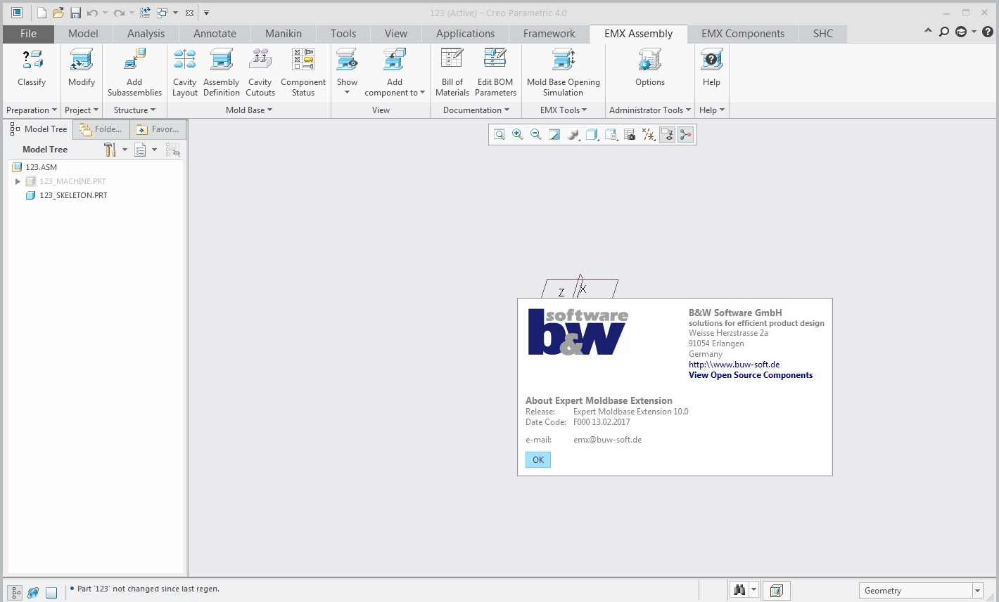
PTC Creo Expert Moldbase Extension 10.0 F000 for Creo 2.0-4.0 x86 x64 full
working with PTC Creo Expert Moldbase Extension 10.0 F000 for Creo 2.0-4.0 x86 x64 full license
Design with PTC Creo Expert Moldbase Extension 10.0 F000 for Creo 2.0-4.0 x86 x64
Creo Expert Moldbase Extension contains detailed customized packages of plates and the individual elements of the leading suppliers to the requirements basic standards in this field.
When creating Creo Expert Moldbase Extension model unit automatically creates an assembly drawing, the specification and drawings of slabs considering ESKD requirements.
Massing components can be created directly in Creo Expert Moldbase Extension or use formative components created in CreoTool Design module.
Creo Expert Moldbase Extension has a dedicated graphical user interface with a two-dimensional schematic view of a ready-made designs of model units, as well as individual components. It is possible to create and use their design, components, types of used injection molding machines, to get to the base of its data providers.
Selection of the main parameters of mold components is carried out in two-dimensional mode. If necessary, specify the placement options of a component designer refers to the three-dimensional structure. This approach significantly accelerates the development of molds.
Typically, full three-dimensional model of a mold assembly made in plates with holes, slots, etc.. G. In an automated form. Moreover, all the holes and grooves are dependent – when the component is such that these structural elements were made, they are also removed. When resizing and places the components layout, these geometric konstruktivy automatically rebuilt.
Creo Expert Moldbase Extension automatically places fasteners, calculates the length of the pushrods and signs, creating cutouts along the contour of the part. To facilitate the visualization Creo Expert Moldbase Extension allows you to enable / disable the display of all components.
The Creo Expert Moldbase Extension has a mechanism of disclosure of the mold with the help of animation, with the analysis of the components in an intersection. Carrying out the following calculations:
comparison machine of compression force and pressure created within the mold;
force on the wedge when it is moved (in the mechanism of the movable rod) at a predetermined course;
the length of the wedge;
the angle of inclination of the pusher;
delay (when double-disclosure model unit);
the total project cost in the manufacture of molds.
Main advantages
High performance in the design of the model unit because constructor creates a mold of the prefabricated components of adaptive – “cubes” that have already been created drawing templates.
Reducing the probability of errors, because the placement of components and execution of all necessary cut-outs with appropriate clearances fully automated.
User interface with two-dimensional visualization of changes enables fast study of the mold without any extra time spent on the regeneration of a three-dimensional model.
Development of molds for concrete casting machine with the calculation of the required clamping force.
Automated creation of the control program to handle the holes in the plates.
Calculating the cost of the mold.
Creating a private library plates, components, structural arrangements of a dialogue and the model blocks.
The rapid development of the module, interactive reference guide to the animations.
Key features
Automatic component placement mold, followed by removal of the material in the plates.
Automatic generation of the specification, drawings and assembly drawing boards.
Automatically create associative hole tables in drawings.
Creating animation mode mold sampling of interconnectivity components.
Libraries of standard blocks molds and individual parts of the leading suppliers: DME, DMS, EOC, Futaba, Misumi, HASCO, KLA, Meusburger, Pedrotti, Rabourdin, Strack, FCPK and GOST following nomenclature libraries:
construction of model units (a standard set of types of all sizes, double pushing, double disclosure);
set of plates and insulation;
centering elements (hub, column);
shanks;
locks;
runner and the central hub;
pushers and kontrtolkateli;
stops;
fasteners;
pins;
a support;
circuits and elements of the cooling system;
the movable rod mechanisms;
tilt mechanism pushed;
dual mechanisms of disclosure;
transmission mechanisms for threaded models;
schemes hot runner systems, nozzles, manifolds, flanges.
Create custom libraries with their own types of structures and details of molds.
For download this EMX 10 full crack, click download sysmbol to take this full license soft. The link will be appeared after your check out to support me maintain this website.

For any problems, contact admin for support: [email protected]
Thanks