download Keysight Suite 2017 32bit 64bit full crack 100% working

download Keysight Suite 2017 32bit 64bit full crack 100% working

Link download MBP 2017 x86 x64 full license forever

Download MQA 2017 win32 win64 full crack multilanguage

Keysight Suite 2017 32bit 64bit full
Keysight Suite 2017 – MBP 2017 32bit 64bit full
Working with Keysight Suite 2017 - MQA 2017 x86 x64
Working with Keysight Suite 2017 – MQA 2017 x86 x64 full

MBP 2017
Model Builder (MBP) – a program for modeling devices
The Model Builder (MBP) software is a complete solution that automates and flexibly simulates silicon-based semiconductor devices. The MBP program includes powerful built-in capabilities for modeling and defining device parameters, as well as an open interface for configuring the simulation strategy. The unique Task Tree architecture allows to adapt the process of model extraction to specific data and enables developers to use modern competitive modeling techniques.
Key Benefits of Model Builder
• Ready-to-use solution for creating SPICE models
• A set of software packages for model extraction for field MOSFETs, bipolar transistors, diodes and passive components
• Supports modern models, including BSIM6, BSIM-IMG, BSIM-CMG, etc.
• Ability to create models of aging, models of operation under conditions of overload, models of high-voltage devices
• Possibility to automate and customize the extraction process
• User-friendly user interface and a wide range of modeling support programs
MQA 2017
Model Quality (MQA) is a model quality control program
The Model Quality Check Program (MQA) allows developers and manufacturers of integrated circuits to verify, compare and document SPICE models. The MQA program provides the industry with a standard for ensuring the quality of SPICE models and an open communication environment. The program allows you to automatically verify the validity, comparison and documentation of models and guarantees high quality design.
Key Benefits of MQA
• Ready-to-use adaptable solution for checking the quality of SPICE models
• Automatic validation and high quality SPICE models
• Debugging SPICE simulation results
• Verification of the validity of factory models; Creation of detailed reports on the quality control of models
• Comparison of differences between model versions, SPICE simulators and production technologies
If you want to download this Keysight Suite 2017, please click to DOWNLOAD symbol and complete check out a little help my website is maintained. The download link is appeared automatically when you complete check out.
CLICKDOWN.ORG Download CAD CAM CNC software e1600323925412
Please see youtube video for download instruction by open *.txt file and copy youtube video link paste to your browser If you don’t know how to download.
Inside folder Keysight Suite 2017, already have crack’s file and instruction how to install this version of Keysight Suite 2017 step by step. I guarantee you can install Keysight Suite 2017 successfully if you follow that instruction.
If you also can not install it or any problems, please contact to me by email: [email protected], then I will help you to install software by teamviewer.
Thanks a lot

download SolidCAM 2009 SP5 32bit 64bit full crack 100% working

download SolidCAM 2009 SP5 32bit 64bit full crack 100% working

link SolidCAM 2009 SP5 for solidworks 2004-2012 full license

SolidCAM 2009 SP5 for solidworks 2004-2012 win32 win64 multilanguage full

SolidCAM 2009 SP5 x86 x64 full

SolidCAM is a new generation CAD / CAM system developed by Israeli firm SolidCAM Ltd (Official distributor in Russia – Consistent Software). This system is a complete solution for automation of metalworking production. With the use of a wide range of strategies of turning, milling, turning and electro-erosion machining offered by SolidCAM, a technologist can quickly prepare the necessary set of control programs for machining the product.
Functionality of SolidCAM
2.5-axis milling
SolidCAM provides high efficiency and accuracy of 2.5-axis milling of parts. Different processing strategies for elements such as contour, sampling (with islands) and groove, as well as various types of hole machining are supported: drilling, reaming, threading, etc. The system has a wide range of possibilities for 2.5-coordinate processing of analytical surfaces.
3-axis milling
SolidCAM provides a wide range of tools that can be effectively used to handle products with complex geometries (stamps, molds) and prismatic parts. As a geometry for 3-axis machining a three-dimensional surface or solid model is used. The system supports various types of roughing and finishing strategies, such as raster processing with a specified or automatically determined raster angle, equidistant processing, projection processing, waterline processing, etc.
In addition to the already listed capabilities of 2.5- and 3-coordinate processing, SolidCAM offers tools for identifying and finalizing areas that were not processed in previous transitions. It is possible to create a database of standard technological processes. Once created, this parameterized technological process can be repeatedly used in the future, which significantly reduces the time of preparation of production, increases the reliability of the developed programs, unifies the style of technological developments, guarantees the use of only optimal processing technologies and ensures the production independence from the human factor. The absence of cuttings is guaranteed by the availability of means of control and visualization of machining.
Multi-axis machining
SolidCAM offers various tools for creating control programs for multi-axis machining at 4- and 5-axis machining centers. The model is installed in the user defined processing plane, after which the system automatically calculates all the necessary displacement and rotation parameters for the workpiece zero. As a result, the preparatory-final transition time is significantly reduced and the accuracy of the processing is increased.
Turning and turning-milling processing
SolidCAM has a wide range of functions to automate the creation of control programs for turning and turning and milling. SolidCAM supports various types of tools, which allows you to effectively produce longitudinal turning, trimming, grooving, etc. In addition, SolidCAM allows you to automatically produce roughing and finishing of complex contours. Support for the rotating tool allows you to perform milling and drilling transitions at machining centers.
Electroerosive processing
The proposed set of strategies of SolidCAM wire EDM allows the processing of external and internal circuits with a constant and variable angle. There is a possibility of 4-axis machining. A special algorithm prevents the falling of the processed material. SolidCAM provides the user with the means to control the physical processing parameters along the whole path of the wire.
If you want to download this SolidCAM 2009 SP5 full, please click to DOWNLOAD symbol and complete check out a little help my website is maintained. The download link is appeared automatically when you complete check out.
CLICKDOWN.ORG Download CAD CAM CNC software e1600323925412
Please see youtube video for download instruction by open *.txt file and copy youtube video link paste to your browser If you don’t know how to download.
Inside folder SolidCAM 2009 SP5, already have crack’s file and instruction how to install SolidCAM 2009 SP5 step by step. I guarantee you can install SolidCAM 2009 SP5 successfully if you follow that instruction.
If you also can not install it or any problems, please contact to me by email: [email protected], then I will help you to install software by teamviewer.
Thanks a lot

download Delcam PowerMILL 2012 SP7 x86 x64 full crack 100% working

download Delcam PowerMILL 2012 SP7 x86 x64 full crack 100% working

link PowerMILL 2012 SP7 win32 win64 full license forever

PowerMILL 2012 SP7 x86 x64 32bit 64bit full high speed downloading

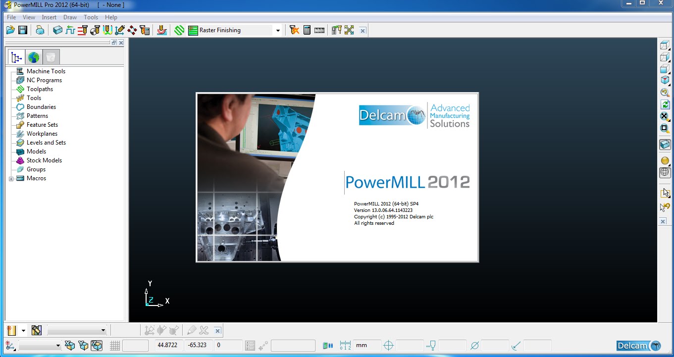
Working with Delcam PowerMILL 2012 SP7 x86 x64 full

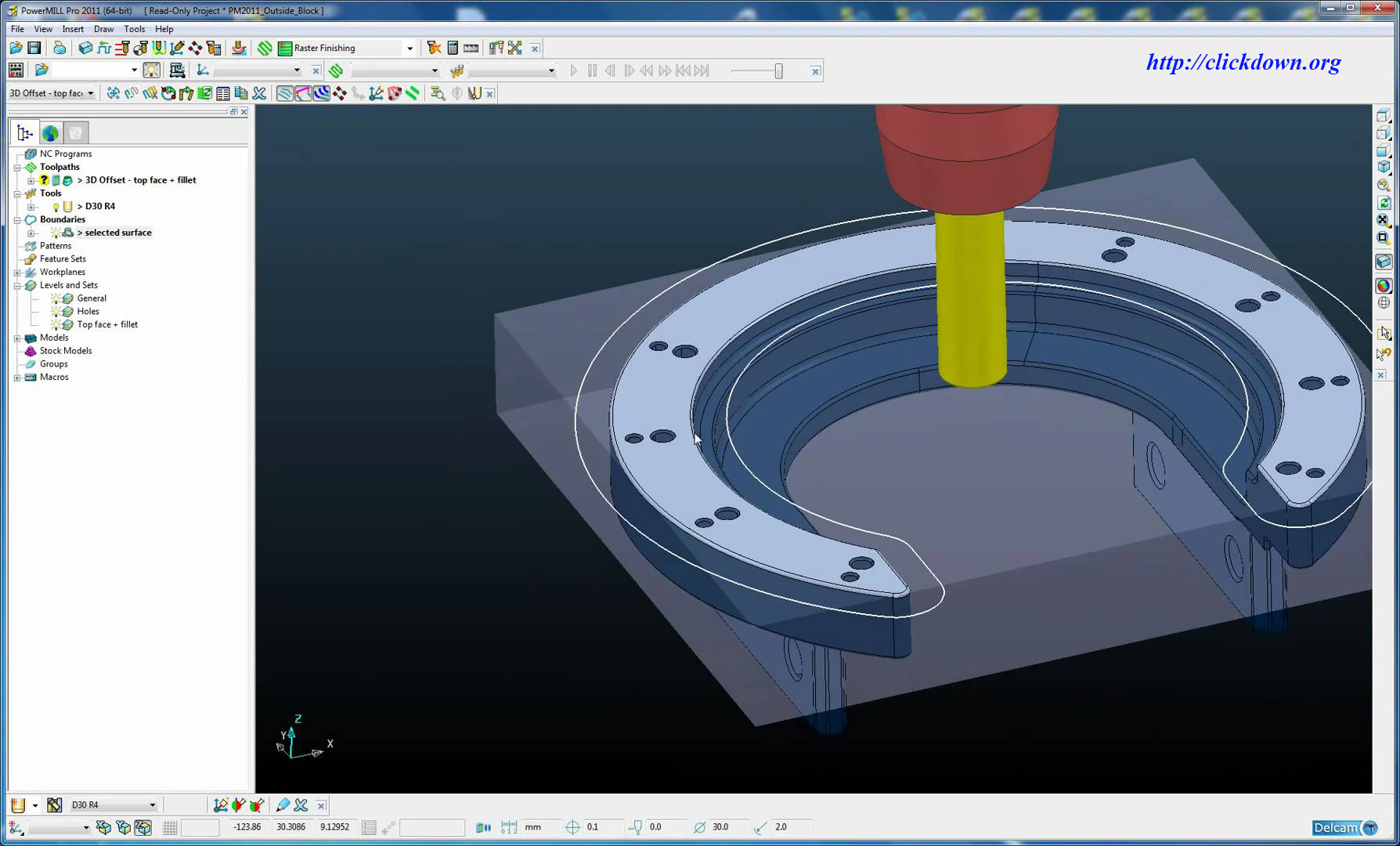
Delcam PowerMILL is an independent CAM-system for the preparation of highly effective control programs for CNC milling machines, which allows you to quickly create the path of the tool without sloughing on the math, using 2.5D machining, 3-axis machining or multi-axis simultaneous machining. Then these trajectories can be checked for collisions with other models (for example, clamps) and a cartridge, before outputting the trajectory to the tap-files.
PowerMILL has a wide range of possibilities for reading CAD files. It supports IGES, VDA and STL formats, which allows you to import data from any CAD system that supports these formats.
Using the PowerMILL simulation, you can load the entire machine in order to check the trajectories and visualize the actions of the machine and tool from different points of view.
PowerMILL is the leading software CAM product for manufacturing complex shapes, often found in the instrumental, automotive and aerospace industries.
Main features:
2D processing
2D processing operations, such as flat surface machining, chamfering and hole drilling,
Are an integral part of the process of manufacturing complex parts. Being world
Leader in the field of innovative high-speed and multi-axis processing, PowerMILL contains
High-performance, comprehensive functionality for 2D processing.
In PowerMILL 2D pocket milling and profile processing are performed directly on the curves of the 2D frame, which allows you to quickly handle the bosses, pockets and side elements.
The user can specify the number of radial and axial movements, and PowerMILL automatically compensates for the tool radius.
Pocket milling and profile processing functions support a 3D model of the rest of the material, so PowerMILL can be used for 2D chamfering and boring operations.
All 2D elements can be fully tested for incidents and collisions using the 3D model.
Highly efficient roughing
High efficiency of roughing strategies is achieved due to a constant load on the tool and smooth toolpaths without sudden changes in the cutting direction.
As the roughing area is removed from the theoretical surface of the finished part, Delcam’s patented technology smoothes the trajectories of the rough passages.
PowerMILL automatically removes small scallops of the remaining material, adding smooth tool passes to these areas.
Undeveloped scallops can appear at certain ratios of the radius of the trajectory and the pitch between the tool passes.
Using the full 3D model of the rest of the material in PowerMILL provides stable cutting modes and reduces unnecessary travels through the air.
At any stage of processing, the remaining material can be calculated and visualized, which makes it easier to select the appropriate strategies and tools for removing the remaining material.
High-speed finishing
High speed finishing controls the smoothing of the trajectory and the load on the tool.
PowerMILL reduces sudden changes in the direction of the tool.
3D-offset processing
3D-offset processing provides an excellent quality
Surface, allowing you to control the distance between successive
Passages along the height of the scallop. This leads to a different step
Between the aisles on steep and flat surfaces.
Finishing with 3D spiral offset prevents the appearance of
Marking by maintaining a constant tool contact
With the surface of the part with its continuous smooth motion along a spiral.
Finishing the strategy ‘Sheer + Slope’
Optimized strategy ‘Sheer + Slope’ combines trajectories,
Created by a 3D displacement on gently sloping areas, and processing ‘C constant Z’ on vertical walls, automatically creating optimal trajectories.
PowerMILL controls overlapping areas of both strategies.
Parametric processing
The parametric offset creates trajectories for processing the surface with a variable, rather than a constant step.
This strategy allows you to process the entire area without sudden changes in direction.
Five-axis machining
Five-axis machining strategies PowerMILL provide an excellent finish surface quality,
Exclude unpredictable movements of the working parts of the machine and significantly shorten development time
Control programs. Reducing the delivery time of finished products, increasing productivity
Labor and increased profitability make the five-axis machining very attractive
Positional (3 + 2) processing
The deviation of the tool axis from the normal to the surface with an angle of attack or inclination not only improves the cutting modes, but also allows processing more inaccessible areas. Intuitive user interface PowerMILL makes it easy to program positional processing, enabling you to process parts in one installation more efficiently and achieve high quality finishing.
Continuous five-axis machining
Strategies for continuous five-axis machining of PowerMILL allow for full control over the orientation of the tool axis relative to the workpiece. These strategies are ideal for pruning and drilling composite parts, as well as for machining high-wall sideways cutters. It is also possible to process complex parts in one installation, which significantly reduces production costs and saves time.
Five-Axis Finishing
When finishing the angular zones, you can take advantage of the positional (3 + 2) and continuous five-axis strategies of PowerMILL for reliable and safe removal of all the remaining material. Automatic functions for finishing corners themselves determine where to process the steep or gently sloping areas of the remaining material, which shortens the programming time, extends the tool life and improves the quality of the treated surface.
Automatic collision avoidance
PowerMILL collision avoidance feature automatically
Deflects the axis of the instrument from obstacles to a specified distance.
When the obstacle is traversed, the tool axis returns to the original orientation.
In addition to avoiding obstacles, this function is also used when processing undercuts.
Blades, mono-wheels and impellers
A key feature of the PowerMILL CAM system is that it allows you to simply perform very
Complex operations. This becomes especially noticeable in the processing of blades, mono-wheels and impellers.
Automated approach PowerMILL allows you to effectively program the processing of complex
Details with minimal effort on the part of the user. Intelligent prevention function
Collision ensures the creation of smooth trajectories, eliminating slashes and collisions
Tool with workpiece, machine elements and fasteners.
Adaptive machining replaces the traditional sequence
Technological processes (from CAD – to CAM – to the CNC machine – to the final
Control of accuracy) to a progressive integrated approach, in which
Interoperational accuracy control is performed directly on the CNC machine,
With the help of measuring heads. The solution for adaptive machining,
Provided by Delcam, can be customized to the features of production,
Ensuring that the accuracy of the manufacture of parts corresponds to the required quality.
The technology of adaptive machining from Delcam allows you to perform repairs
Front and rear edges of blades of gas turbine and turbojet engines.
Channel processing
The PowerMILL channel processing module is a specialized solution for fast and efficient
Processing of the cylinder heads and other parts with internal channels. Despite,
That initially this solution was developed for processing channels in engines, it can be used
For the creation of closed monocols, impellers and other hollow forms.
PowerMILL begins processing channels using a three-axis or positional (3 + 2) strategy for maximizing the fastest retrieval of material using a tool with a minimum length that provides a better result. You can use the technology of automatic collision avoidance PowerMILL to convert triaxial trajectories into their five-axis equivalents for processing all hard-to-reach parts of the channel. When PowerMILL reaches the processing limits in one direction, it automatically executes the approach from the opposite side of the channel, using the same processing strategy to remove material throughout the channel.
Path patterns
PowerMILL trajectory templates allow standardizing the parameters of control programs for the entire enterprise.
You can use mathematical expressions to specify the parameters of the pattern templates. For example, you can specify the step size as a percentage of the tool diameter so that it is automatically calculated each time a new tool is used. Customizing the PowerMILL trajectory templates makes programming more efficient, reducing the number of mouse clicks and reducing the chance of a programmer-technologist error.
Customizable toolbars
In PowerMILL, you can easily create custom toolbars to reduce the number of mouse clicks required to perform frequently used functions, especially those contained in the PowerMILL menu. Using custom toolbars makes programming easier and faster.
Macros
Macros contain a sequence of commands for automating typical operations. Macros can be created by writing a sequence of operations at the time they are executed in PowerMILL or typing commands in a text editor. Macros can be used for visualization, fine tuning of leads, taps and transitions, setting parameters for control programs, automating the execution of frequently used processing sequences, and much more.
To automate the decision making process, you can create complex macros with dialog boxes and use If-Else type conditional operators, loops with Do-While conditions, and other programming functions.
3D modeling for processing
The PowerMILL Modeling module contains extensive functionality for 3D modeling, necessary
To restore, modify and edit CAD-models received from customers.
The available 3D modeling tools allow you to fix any problems with geometry even before,
As you begin to develop the UE, without involving third-party CAD-systems.
A full set of tools for restoring and editing CAD-models allows you to find and fix
Any problems in the geometry of surfaces that arose in the process of 3D modeling or import.
Interactive tools for analyzing 3D models identify problem areas that can cause difficulties in subsequent processing,
And functions of fine-tuning CAD-models allow to make necessary corrections to the geometry.
The use of PowerMILL for the manufacture of electrodes
The Delcam Electrode module helps in the shortest possible time to design complex electrodes for electro-erosion processing and represents a completely completed solution that covers the entire cycle of electrode production – from design to final precision control.
A single TRODE file contains all the necessary processing information, which simplifies data management and ensures uniformity of processes.
The Delcam Electrode application allows the use of new direct modeling tools,
Based on the technology of solid-state 3D modeling, to extract, edit and create electrodes.
You can create an electrode based on the information about the workpiece, the holder, the interelectrode gap and the parameters of EDM;
Create accompanying documentation for the electrode.
If you want to download PowerMILL 2012 SP7 x86 x64, please click to DOWNLOAD symbol and complete check out a little help my website is maintained. The download link is appeared automatically when you complete check out.
CLICKDOWN.ORG Download CAD CAM CNC software e1600323925412
Please see youtube video for download instruction by open *.txt file and copy youtube video link paste to your browser If you don’t know how to download.
Inside folder PowerMILL 2012 SP7 x86 x64, already have crack’s file and instruction how to install PowerMILL 2012 SP7 x86 x64 step by step. I guarantee you can install PowerMILL 2012 SP7 x86 x64 successfully if you follow that instruction.
If you also can not install it or any problems, please contact to me by email: [email protected], then I will help you to install software by teamviewer.
Thanks a lot

download Delcam PowerMILL 2011 SP11 32bit 64bit full crack forever

download Delcam PowerMILL 2011 SP11 32bit 64bit full crack forever

link Delcam PowerMILL 2011 SP11 win32 win64 full license

Delcam PowerMILL 2011 SP11 x64 high speed downloading

PowerMILL 2011 SP11
PowerMILL 2011 SP11 x86 x64
Delcam PowerMILL 2011 SP11
Program with Delcam PowerMILL 2011 SP11 full

Description: PowerMILL is an independent CAM-system, which allows you to quickly create the trajectories of UE without sloughing on the metal models, using 2.5D processing, 3-axis processing or multi-axis simultaneous processing. Then these trajectories can be checked for collisions with other models (for example, clamps) and a cartridge, before outputting the trajectory to the tap-files.
PowerMILL has a wide range of possibilities for reading CAD files. It supports IGES, VDA and STL formats, which allows you to import data from any CAD system that supports these formats.
Using the PowerMILL simulation, you can load the entire machine in order to check the trajectories and visualize the actions of the machine and tool from different points of view.
Enhancements for Curve Editor
Several improvements have been made to the Curve Editor toolbar:
• Now you can create an arc that is tangent to existing lines and arcs, as well as an arc at given points, using the Arc button on 3 elements.
• You can now change the fillets in two ways.
• Now you can create a line that is tangent to the curve.
• This also applies to templates and borders.
Transformation of a trajectory and a skeleton
Transformation of the trajectory is now much easier, in addition, you can apply several transformations simultaneously.
• The new toolbar contains options for offset, reflection, rotation or template transformation, and the preview image allows you to immediately view the necessary transformations.
• A similar function was added in the curve editor for templates and borders.
Trajectory \ boundary outside the workpiece
Trajectories and boundaries can now extend beyond the workpiece.
This function allows you to ensure that all parts of the path are processed.
Improvements for blanks
Several improvements have been made for the shape of the blank:
• When calculating the size of the workpiece, you can now take into account the previous surfaces.
• The workpiece or model can now be saved as DMT or STL files.
Determination of the cartridge / shank
The cartridge and shank can now be set directly from the template.
Complex tools in the assembly can now be defined easily and quickly using the PowerMILL curve editor or through imported profiles.
You can also draw a shank and a chuck when creating the tool with the cursor.
Material Model Accounting
Accounting for the material model is a great new option available in all finishing dialogs to accurately control the optimal amount of material that you want to process. Advantages of this new option: –
Prevents tool damage that may occur when processing excess material
Allows higher feed rates, as excessive tool contact is avoided
The processing time is shortened by removing segments of the trajectory that process a very small amount of material or do not process anything at all.
Fixed angles of the tool axis
In the Tool Axis dialog, a new option is available to lock the rotary axis of the machine to avoid unnecessary movement of the tool axis.
By reducing any unnecessary movement of the machine axis, you will see improvements in the quality of the surface finish and in the processing time.
The Fixed Angle option is available for all tool axis definitions except those that have the tool axis specified as Saving Direction or Automatic.
Feed and tap feeds
Feed / tap feeds can now be set independently of the main working feedrate.
A slower entry and exit from the material will help to increase tool life and reduce the risk of damage to the part with brittle material.
Clever choice
Similarly to the functions of drilling methods in PowerMILL, Smart Selection allows you to import data and automatically select combinations of surfaces for processing based on the color, level, or model name. This selection can be added to the set of allowances and saved in the trajectory template.
Examples of using this function:
Process yellow or red surfaces at level 15.
Ignore the “xxx” model surfaces that are not green.
Improved boundary trajectory constraint
Significant improvements have been made in how trajectories are limited by boundaries.
Trajectories are now truncated using the 3D constraint method, giving more accurate results.
If you want to download PowerMILL 2011 SP11, please click to DOWNLOAD symbol and complete check out a little help my website is maintained. The download link is appeared automatically when you complete check out.
CLICKDOWN.ORG Download CAD CAM CNC software e1600323925412
Please see youtube video for download instruction by open *.txt file and copy youtube video link paste to your browser If you don’t know how to download.
Inside folder PowerMILL 2011 SP11, already have crack’s file and instruction how to install PowerMILL 2011 SP11 step by step. I guarantee you can install PowerMILL 2011 SP11 successfully if you follow that instruction.
If you also can not install it or any problems, please contact to me by email: [email protected], then I will help you to install software by teamviewer.
Thanks a lot

download Autodesk SketchBook for Enterprise 2018 v8.3.1 x64 Full crack

download Autodesk SketchBook for Enterprise 2018 v8.3.1 x64 Full crack

link Autodesk SketchBook for Enterprise 2018 v8.3.1 win64 full license

Autodesk SketchBook for Enterprise 2018 v8.3.1 Final
Working with Autodesk SketchBook for Enterprise 2018 v8.3.1 Final

Autodesk SketchBook Pro – turns your computer, laptop or tablet into an ideal tool for drawing and drawing. Thanks to the professional sketching tools, even novice users will be able to master the technique of working with the program in the first few minutes. Sketchbook is a new generation graphics program that provides all the tools you need to move from drawing on paper to using the digital environment.
“” “” “” “” “” “” “” “” “” “” “” “” “” “” “” “” “” “” “” “” “” “” “” “” “” “” “” “” “” “” “” “” “” “”
Capabilities:
• Library of brushes, as well as creating and customizing your own brushes
• Additional layer functions
• Copic Color Library
• Mixing modes
• Fast conversion, the tool “Distortion”
• Symmetry, ruler, ellipses
• Additional Perspectives
• Synthetic brushes and brushes for mixing
• Dynamic gradient fill
• Optimized use of the pen, brushes
• Animation of the cineographer
• Custom size of the active window up to 64 MP
• Brushes allow you to make notes and add comments.
• You can upload and view images, as well as digital photos.
• Ability to send pictures and notes to colleagues and customers.
• Use in industries: printing, industrial design, automotive, architecture, creating illustrations, design, storyboarding, reviewing, etc.
If you want to download Autodesk SketchBook for Enterprise 2018 v8.3.1, please click to DOWNLOAD symbol and complete check out a little help my website is maintained. The download link is appeared automatically when you complete check out.
CLICKDOWN.ORG Download CAD CAM CNC software e1600323925412
Please see youtube video for download instruction by open *.txt file and copy youtube video link paste to your browser If you don’t know how to download.
Inside folder Autodesk SketchBook for Enterprise 2018 v8.3.1, already have crack’s file and instruction how to install Autodesk SketchBook for Enterprise 2018 v8.3.1 step by step. I guarantee you can install Autodesk SketchBook for Enterprise 2018 v8.3.1 successfully if you follow that instruction.
If you also can not install it or any problems, please contact to me by email: [email protected], then I will help you to install software by teamviewer.
Thanks a lot

error: Content is protected !!
Scroll to Top