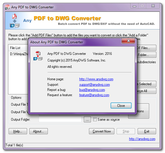
download DATAKIT CrossManager 2017.3 x86 x64 full crack forever
download DATAKIT CrossManager 2017.3 x86 x64 full crack forever
link download DATAKIT CrossManager 2017.3 win32 win64 full license
 Working with DATAKIT CrossManager 2017.3 full license
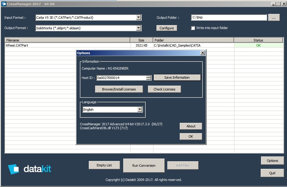
Description: A translator from different CAD formats
Cross Manager is a Stand Alone software that converts files from most CAD formats.
With Cross Manager, You just have to select a CAD file in the software for convert it automatically in the format you need.
Inputs:
3Shape DCM, ACIS, CADDS, CATIA V4 2D, CATIA V4 3D, CATIA V5 2D, CATIA V5 3D, CATIA V6 2D, CATIA V6 3D, Cercon, CEREC – Sirona Dental, CGR, I-deas, IGES, Inventor, JT, Parasolid, PLMXML 3D, Procera ‘ProE / Creo Parametric 2D, ProE / Creo Parametric 3D, Rhino 4, Rhino 5, Robcad, Solid Edge, SolidWorks 2D, SolidWorks 3D, STEP, UG NX 2D, UG NX 3D, VDA
Outputs:
CIS, CADDS, CATIA V4 3D, CATIA V5 3D, CGR, COLLADA, DXF, IGES, JT, Open CASCADE, Parasolid, PDF 2D, PDF 3D, Robcad, SolidWorks 3D, STEP, STL, Unisurf, VDA, VRML.
If you want to download DATAKIT CrossManager 2017.3 x86 x64, please click to DOWNLOAD symbol and complete check out a little help my website is maintained. The download link is appeared automatically when you complete check out.

Please see youtube video for download instruction by open *.txt file and copy youtube video link paste to your browser If you don’t know how to download.
Inside folder DATAKIT CrossManager 2017.3 x86 x64, already have crack’s file and instruction how to install DATAKIT CrossManager 2017.3 x86 x64 step by step. I guarantee you can install DATAKIT CrossManager 2017.3 x86 x64 successfully if you follow that instruction.
If you also can not install it or any problems, please contact to me by email: [email protected], then I will help you to install software by teamviewer.
Thanks a lot